

I. Why Gate Valves Require Dedicated Lock‑Out Devices
Within the industrial LOTO (Lockout‑Tagout) system, gate valves are one of the most common energy‑isolation points. Piping may carry steam, high‑pressure water, chemicals or flammable gas. Unless a valve is securely fixed in the closed position, maintenance personnel working downstream are constantly exposed to the risk of accidental valve reopening.
However, gate valves rank among the most difficult isolation points to secure. Unlike circuit breakers with standard locking holes or push‑buttons with recesses, gate valves are fitted only with a round handwheel that can be rotated to open the valve with minimal effort. A simple warning tag provides no physical restraint at all. A physical device must be used to lock the handwheel in place so that reliable energy isolation can be achieved.
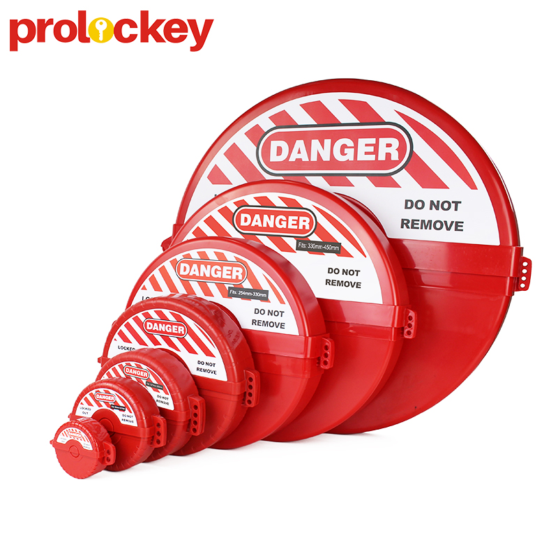
A valve lockout device is designed for exactly this purpose. It encases or clamps onto the valve handwheel to prevent rotation, and is secured with a safety padlock. This converts a “closed valve” into a “valve that cannot be opened”.
II. Step One for Selection: Identify Your Valve Properly
Incorrect device selection is the leading cause of failed gate‑valve lockout. Three key parameters must be confirmed before purchasing:
- Handwheel Diameter This is the core parameter for selecting a gate‑valve lockout. Lockout devices are graded according to handwheel diameter, with standard ranges covering 1 inch up to 13 inches and above. Adjustable‑range units are required for sizes beyond standard coverage. Match the measured handwheel diameter against the device’s specification range. It is better to allow slight clearance than to force‑fit: excessive tightness prevents installation, while excessive looseness results in insecure clamping.
- Handwheel Type The two most common variants are spoked handwheels (with open gaps between spokes) and solid‑disc handwheels (solid or nearly‑solid circular face). Lockout devices for spoked handwheels clamp into the gaps between spokes. Solid‑disc handwheels require two‑piece enclosure‑style locks that close around the full circumference. These two designs are structurally incompatible; buying the wrong unit will render it unusable.
- Valve Category Strictly speaking, gate‑valve lockout devices are intended exclusively for gate valves. On‑site cross‑use with ball valves, butterfly valves and globe valves frequently occurs, yet each of these requires a distinct lockout mechanism. Ball‑valve locks restrain lever rotation, while butterfly‑valve locks secure the operating handle. If your pipe rack contains mixed valve types, purchase dedicated locks for each category rather than relying on a single universal‑fit solution.
III. Step Two for Selection: Choose the Right Structure
Three main structural designs are available for gate‑valve lockout devices, each suited to different scenarios:
- One‑Piece Universal Gate‑Valve Lock The most common entry‑level solution. Fabricated as an injection‑moulded engineering‑plastic housing with movable internal jaws to grip handwheel spokes or edges. It covers a relatively wide diameter range (for example 1 – 6.5 inches) and offers high versatility, making it ideal for older facilities with a large variety of existing valve sizes. The drawback is that the clamping jaws may fail to grip highly irregular‑shaped handwheels.
- Two‑Piece Enclosure‑Style Gate‑Valve Lock Consists of upper and lower shells that fully enclose the handwheel, fastened together with screws before padlocking. This design tolerates nearly all handwheel profiles and works equally well for spoked and solid‑disc types, delivering high locking strength. It is the mainstream option for high‑safety‑risk sites such as chemical plants and power stations. The downside is that separate units must be purchased for distinct diameter bands, with each device covering only a narrow size range.
- Adjustable‑Range (Multi‑Fit) Gate‑Valve Lock Equipped with sliding jaws or extendable arms to accommodate a broad spectrum of handwheel diameters, typically from 2 inches to 13 inches. Perfect for contractors and maintenance crews working at multiple sites with unknown valve specifications, as a small set can cover most encountered valves. Its disadvantages include a more complex build and longer on‑site adjustment time for every application.
IV. Step Three for Selection: Material and Colour Considerations
Material: Most commercial gate‑valve locks are manufactured from engineering plastics such as modified ABS or nylon. Plastic‑based lockouts are non‑conductive, rust‑proof, resistant to most chemical agents and lightweight — well suited to long‑term exposure in industrial piping environments. For steam valves operating at elevated temperatures, verify the device’s temperature rating (standard engineering plastics generally sustain continuous exposure between 80 °C and 100 °C); metal‑constructed lockouts should be selected above this threshold. For environments with strong acids or alkalis, cross‑check material chemical‑resistance data.
Colour: Gate‑valve locks are available in multiple standard colours including red, yellow, blue, green and orange. Align your colour choices with your facility’s internal LOTO colour‑coding scheme. For instance, red commonly signals “Isolated — Do Not Operate”, and yellow may indicate “Contractor‑Applied Lockout”. Distinct colours enable staff to identify isolation status visually from a distance along pipe corridors.
Post time: Aug-29-2026


